Relay 2 Wire Door Lock Actuator Wiring

Door Lock Actuator Wiring Diagram Wellread Me And Power Electrical Wiring Diagram Magnetic Door Lock Door Locks

How To Wire Relays Door Locks Actuators Reverse Polarity Negative Switch Trigger B Automotive Repair Automotive Electrical Boat Wiring

Technical Wiring Diagrams Door Locks Doors Diagram

Posted Image Relay Actuator Installation

Awesome Wiring Diagram Of Door Access Control System Diagrams Digramssample Diagramimages Wiringdiagramsample Wiringdiagram Che Diagram Power Repair Guide

Unusual Freightliner Power Window Wiring Diagram Images Beautiful And Motor Trailer Wiring Diagram Windows Automotive Electrical

The actuator on the passenger door cut off the white brown and black wire and on the driver door ground the black wire and tie in the white and brown wire on the blue and green.
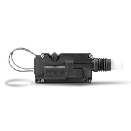
Relay 2 wire door lock actuator wiring. 5 wire actuator diagram. The items we have are a cfd universal car power door lock actuator 12 volt motor a docooler car remote central lock locking keyless entry system with remote controllers. This was fairly easy to install i only needed two screws to hold it to the inside of the door and with a couple of creative bends the actuator rod clamped right on to the manual lock unlock rod. I want to use an arduino to activate a two wire actuator automobile power door lock mechanism.
If you are doing a conversion from non power to power locks use the 5 wire to control the other locks. If you reverse the polarity on the actuator and apply power it flips in the other direction. Both motor legs rest at ground at the relays. Same as a hallway light that operates from 2 location in the house.
When power is applied the actuator flips in one direction. Green lock blue unlock. To lock or unlock the vehicle polarity is changed on one motor leg via a positive pulse from a switch alarm keyless entry etc. It will open all the way and door will be closed and then open all the way when the switch is triggered on either end.
The remote has 10 wires coming from its harness. I know enough about electrical wiring to efficiently burn the house to the ground. Door locks actuators reverse polarity positive switch trigger type d relay wiring diagram. Anyone care to help out.
To the coil of the respective relay. Wire up the relays like your diagram and run it to the blue and green wire on the actuator. How to do a relay power door lock get the book at amazon. Trying to figure out the wiring to operate 1 actuator using 2 on on switches.
Actuator has built in limit switches.

Actuatorrevpol Gif 350 200 Car Audio Installation Actuator Remote Door Lock

Best Relay Wiring Diagram 5 Pin Wiring Diagram Bosch 5 Pin Relay Electrical Circuit Diagram Electrical Diagram Electrical Wiring Diagram

Wiring Diagram Relay Power Window Post Date 05 Dec 2018 78 Source Http Wright Here Net Imag Trailer Wiring Diagram Windows Automotive Electrical

288724 Img009 1 Jpg 226 300 Diagram Garage Equipment 98 Chevy Silverado
Jeep Cherokee Power Lock Diagram Jeep Cherokee Jeep Cherokee Xj Jeep Xj

New Arrvier T240 Universal Car Dc 12v 2 4 Doors Wire Heavy Duty Power Door Lock Actuator Auto Locking System Motor With Door Lock System Keyless Keyless Entry

How To Use Relays To Control Linear Actuators Linear Actuator Actuator Linear

Pin By Luc Govaerts On Wairing Horness All Types Electronics Projects Diy Automotive Mechanic Automotive Repair

Universal Car Auto Remote Central Kit Door Locking Vehicle Keyless Entry System With Remote Contronllers Keyless Door Lock Car Alarm Keyless

Burglar Alarm Car Remote Control Central Kit Door Lock Locking Keyless Entry System Universal Car Alarm Security Car El Keyless Entry Systems Car Alarm Keyless

16 Ignition Wiring Diagram Motorcycle Motorcycle Diagram Wiringg Net In 2020 Opel Corsa Trailer Wiring Diagram Alternator

New Oe 2992551 2991727 Ignition Barrel Keys Ignition Switch Barrel Door Lock Barrel For Iveco Daily 2000 2006 Review Door Locks Barrel Switch

90 96 Nissan 300zx Oem Door Lock Timer Unit Relay Module 28451 F9901 Nissan 300zx Timer Nissan

New Bmw E46 Cluster Wiring Diagram Opel Corsa Trailer Wiring Diagram Alternator

1994 Honda Civic Wiring Diagram In 2020 Honda Civic Honda Civic Dx Honda
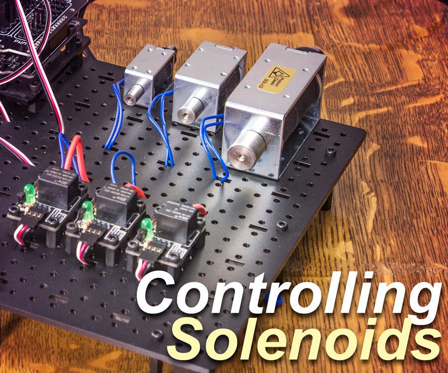
Control A Solenoid With Arduino Arduino Arduino Projects Radio Control Diy

Door Lock Actuator Wiring Diagram Wellread Me And Power Electrical Wiring Diagram Magnetic Door Lock Door Locks

Crimestopper Power Door Lock Module With Images Door Locks Door Accessories Auto Body Repair Shops
Https Encrypted Tbn0 Gstatic Com Images Q Tbn 3aand9gcryl2o4rx6gzta9 Sfpqqa23iuhy0ezhhgeud4fovi Usqp Cau

Arduino Uno How To Use Stepper Motors From Old Printers With L298n Arduino Stepper Motor Printer

28 Off 100 Brand Door Lock Actuator Rear Left Passenger Side Lh Fit For Vw Jetta 4 Golf 4 Mk4 Gti Bora Beelte Polo 3b Volkswagen Jetta Vw Jetta Volkswagen

Toyota Yaris 2016 Fuse Box Location Fuse Box Yaris Toyota

Fingerprint Sensor Lock Style Electromagnet Electronic Lock

Free Ase Certification Practice Tests Freeasestudyguides Com Circuit Camper Van Conversion Diy Practice Testing

Pin On Car Maintenance

Lt1 Wiring Diagram In 2020 Diagram Electrical Diagram Body Tech

Pin On Car Alarm Systems

For Mitsubishi Outlander 2016 2017 2018 Xpander Cruise Control Switch Steering Wheel Control Switch Button Audio Volume Switch Review Mitsubishi Outlander 2016 Mitsubishi Outlander Mitsubishi Outlander 2013

Peugeot 206 Wiring Diagram For Central Door Locking Charming In Peugeot Diagram Doors

84810 60050 8481060050 Power Window Control Switch For Toyota Land Cruiser 100 1998 2007 Review Toyota Land Cruiser 100 Toyota Land Cruiser Land Cruiser

Camco Quick Connect Conversion Kit 57638 The Home Depot Camco Drain Cleaner Propane Accessories

1pc Seeyule 1j4 959 857d 857b Car Power Window Control Switch For Vw Passat Bora Golf Mk4 Mk5 97 09 For Seat Leon Toledo 99 12 Review Vw Passat Seat Leon Volkswagen Models

Rear Right Side Door Lock Actuator For 2001 2005 Lexus 2000 2005 Toyota Echo 69130 30110 4pins Toyota Echo Lexus Toyota Prius

433 Mhz Wireless Remote Control Led Switch Dc 12v 10a 4ch Relay 433mhz Receiver Module For 1527 Lea Remote Control Light Electronic Accessories Electronic Lock

How To Make A Music Player Using Arduino In 2020 Arduino Music Players Simple Arduino Projects

Pin On Arduino

Wifi Internet Controlled Relays Using Esp8266 Quick 30 Minutes Iot Project Iot Projects Arduino Wifi Internet
Directed 524n 12v Accessory Pulse Timer Multicolor Ebay Consumer Electronics Walmart

Volvo L120e Specification Wiring Harness Yahoo Image Search Results Lucu

Arduino Clock With Ds3231 And Lcd1602 Arduino Clock Real Time Clock

Engine Wiring Diagram Jeep Tj Uk Di 2020

This Is Engine Compartment Wiring Diagram For 1981 Trough 1987 Chevrolet V8 Truck Description From Autowiringdiagra Chevy Trucks 1979 Chevy Truck Truck Engine

